
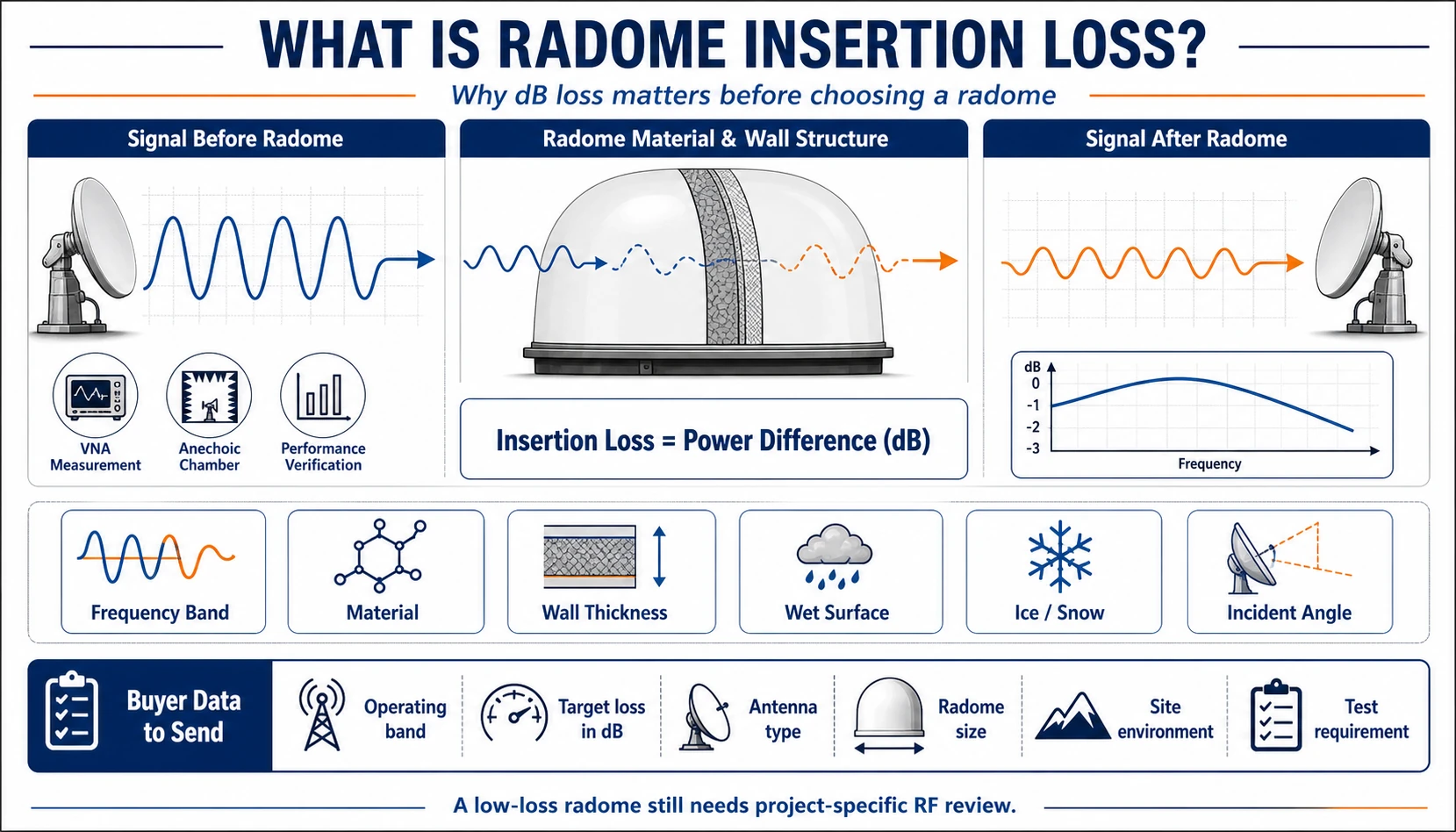
Insertion loss is one of the most important RF terms in a radome project. It describes how much signal power is lost when the electromagnetic wave passes through the radome.
For buyers, the main point is simple: the radome should protect the antenna or radar without reducing system performance beyond the acceptable limit. But insertion loss is not a fixed number for every radome. It depends on frequency band, material, wall thickness, structure, surface condition, incident angle and testing method.
Simple definition
Radome insertion loss is the power difference before and after the signal passes through the radome. It is usually expressed in dB. Lower insertion loss usually means less signal power is lost, but the acceptable value depends on the system and frequency band.
Why buyers should care
A radome may look mechanically correct but still create RF problems if it is not reviewed for the operating band. This matters for radar, satellite communication, weather radar, civil aviation radar and other communication systems.
What affects insertion loss?
| Factor | Why it matters |
|---|---|
| Frequency band | Material and wall structure must match the operating band. |
| Material | Composite, membrane and panel materials interact differently with RF energy. |
| Wall thickness | Thickness can affect transmission and reflection. |
| Surface condition | Rain, wet surface, snow or ice can change performance. |
| Incident angle | Signal path through the radome changes with angle. |
| Structure | Frame geometry, panel joints and wall construction can influence RF behavior. |
Frequency band comes first
When a buyer asks for a “low-loss radome,” the supplier still needs to know the frequency band. L band, S band, C band, X band, Ku band and Ka band do not create the same design assumptions.
Low loss does not mean no engineering review
“Low loss” is not enough as a specification. The buyer should define the target band and allowable loss. Other RF topics may also matter, including reflection, beam distortion, depolarization, transmission variation, wet-surface effects and frequency selective behavior.
How insertion loss is reviewed
Depending on the project, insertion loss can be reviewed through engineering calculation, simulation, material test, sample test or chamber testing. The level of review depends on project risk, application and procurement requirement.
Buyer data to send
- Operating band or exact frequency range.
- Insertion loss target in dB if available.
- Antenna or radar model.
- Radome diameter, height and structure type.
- Application: radar, satcom, weather, ATC or industrial communication.
- Site country, altitude and environment.
- Whether RF testing, simulation or documentation is required.
Common misunderstandings
- “Low loss” without a frequency band is not a complete requirement.
- A physically similar replacement radome may still need RF review.
- Bigger radome size does not automatically mean lower loss.
- Material name alone does not define performance.
- Installation angle, joints, wet surface and ice conditions can matter.
FAQ
Is insertion loss always the same across all frequencies?
No. It can vary with frequency, material and wall structure.
Can I request a quote without a dB target?
Yes, but you should provide the frequency band and equipment type so the supplier can identify what must be reviewed.
Does FRP have lower insertion loss than MSF?
Not automatically. Final performance depends on material, structure, frequency band and project design.
Should insertion loss be tested?
For critical projects, testing or simulation evidence may be required. The need depends on project application and technical acceptance requirements.
Submit RF requirements View technical parameters View RF testing